

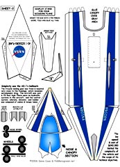
Ames-Dryden-AD1 - $$4.95
This Ames-Dryden AD-1 scissor wing research airplane had a wing that could be pivoted fore and aft to form oblique angles up to 60 degrees.

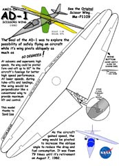
Ames-Dryden AD-1 Scissors (Oblique)-Wing


A program conducted between 1979 and 1982 at the NASA Dryden Flight Research Center, Edwards, Calif., successfully demonstrated an aircraft wing that could be pivoted obliquely from zero to 60 degrees during flight.
The unique wing was demonstrated on a small, subsonic jet-powered research aircraft called the AD-1 (Ames Dryden -1). The research program evaluated the basic pivot-wing concept and gathered information on handling qualities and aerodynamics at various speeds and degrees of pivot.
The so-called variable-geometry wing-used to decrease take-off and landing speeds, increasing cruise and maximum speeds in flight, and reduce fuel burn-arose in baby steps. The carrierbased F-8 Crusader came with a wing that rose upward; the Air Force F-111's wing swept forward and then backward. Same with the Navy Grumman F-14. Those were production airplanes. In 1978 NASA and Ames Industrial Corporation made the experimental AD-1 to test an evolution of variable geometry. The jet's entire wing pivoted. The oblique wing, and idea conceived by Ames Research Center Aeronautical Engineer Robert T. Jones, with detailed design by Burt Rutan, was built from composite materials like most of his airplanes - the jet's wing swept forward up to 60 degrees. Aside from the wing innovation, the cockpit was narrow and compact, but long enough for the pilot to stretch out. Those who flew it found it comfortable, and added that the AD-1 handled fine. NASA called the project useful for research, and even studied the oblique wing for jetliners and fighter planes. Budget restrictions led the agency away from the innovative concept.
Nice effort, nice effect. Hope you have the chance to expand on your line of X-Planes, and the X-planes that weren't CALLED x-planes, like this AD-1, the Douglas Skystreak, D558 II Skyrocket, etc. Cam
Good suggestion. The Douglas Skystreak and the D-558 Douglas Skyrocket are both now available.
Both were designed by Vlad. -Scott Fyn
Thanks so much! I'll let you know how it turns out...Sincerely, Mike Bennett

About Dave Case: I was thinking of what to do next -- my short list would
probably be...Pond Racer (not the easiest, but certainly
beautiful) |
Ames-Dryden AD-1
Project Background
The oblique wing concept was developed by Robert T. Jones, a renowned
aeronautical engineer who, in 1945, proposed the idea of sweeping
wings rearward as a means of delaying the shock waves and compressibility
as an aircraft neared the speed of sound (Mach 1), thus allowing
aircraft to fly more efficiently at high subsonic speeds. At that
time, Jones was an engineer at the NACA (National Advisory Committee
for Aeronautics) Langley facility, now the NASA Langley Research
Center. When Jones issued his oblique wing concept, he was a senior
aeronautical engineer at the NASA Ames Research Center.
 Based on wind tunnel studies, Jones believed that a transport-size
aircraft with an oblique wing would have better aerodynamic performance
than an aircraft with conventional wings at speeds up to Mach
1.4. Studies by Jones also predicted that oblique wing transport
aircraft would have the potential of either increased range or
reduced gross takeoff weight, and would be twice as fuel efficient
as a conventional design.
Based on wind tunnel studies, Jones believed that a transport-size
aircraft with an oblique wing would have better aerodynamic performance
than an aircraft with conventional wings at speeds up to Mach
1.4. Studies by Jones also predicted that oblique wing transport
aircraft would have the potential of either increased range or
reduced gross takeoff weight, and would be twice as fuel efficient
as a conventional design.
The studies by Jones also suggested that subsonic and transonic aircraft with oblique wings would generate less takeoff noise and would generally have better low-speed performance than aircraft with conventional wings. Jones also predicted that an oblique wing aircraft would generate a "softer" sonic boom than a conventional wing aircraft at speeds up to Mach 1.4.
The AD-1 was flown 79 times during the flight test program and demonstrated acceptable flying qualities up to a pivot angle of 50 degrees (in relation to the fuselage). Technical information generated by the AD-1 program would be a valuable source of research data for any future effort to develop a state-of-the-art oblique wing aircraft.
At high speeds, both subsonic and supersonic, the wing would be pivoted at up to 60 degrees to the aircraft's fuselage for better high-speed performance. The studies showed these angles would decrease aerodynamic drag, permitting increased speed and longer range with the same fuel expenditure.
At lower speeds, during takeoffs and landings, the wing would be perpendicular to the fuselage like a conventional wing to provide maximum lift and control qualities. As the aircraft gained speed, the wing would be pivoted to increase the oblique angle, thereby reducing the drag and decreasing fuel consumption. The wing could only be swept in one direction, with the right wingtip moving forward.
The Aircraft
The AD-1 aircraft was delivered to Dryden in February 1979. The
Ames Industrial Co., Bohemia, N.Y., constructed it, under a $240,000
fixed-price  contract.
NASA specified the overall vehicle design using a geometric configuration
studied by the Boeing Commercial Airplane Company, Seattle, Wash.
The Rutan Aircraft Factory, Mojave, Calif., provided the detailed
design and load analysis for the intentionally low-speed, low-cost
airplane. The low speed and cost limited the complexity of the
vehicle and the scope of its technical objectives.
contract.
NASA specified the overall vehicle design using a geometric configuration
studied by the Boeing Commercial Airplane Company, Seattle, Wash.
The Rutan Aircraft Factory, Mojave, Calif., provided the detailed
design and load analysis for the intentionally low-speed, low-cost
airplane. The low speed and cost limited the complexity of the
vehicle and the scope of its technical objectives.
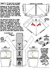
The wing was pivoted by an electrically driven gear mechanism located inside the fuselage, just forward of the engines.
Flight Research
The research program to validate the oblique wing concept was typical
of any NASA high-risk project to advance through each test element
and expand the operating envelope, methodically and carefully. The
basic purpose of the AD-1 project was to investigate the low-speed
characteristics of an oblique-wing configuration.
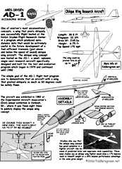
The AD-1 made its first flight late in 1979. The wing was pivoted incrementally over the next 18 months until the full 60-degree angle was reached in mid-198l. The aircraft continued to be flown for another year, obtaining data at various speeds and wing-pivot angles until the final flight in August 1982.
The final flight of the AD-1 did not occur at Dryden, however, but at the Experimental Aircraft Association's (EAA) annual exhibition at Oshkosh, Wis., where it was flown eight times to demonstrate its unique configuration.
Following the flight research, Jones still considered the oblique wing as a viable lift concept for large transoceanic or transcontinental transports. This particular low-speed, low-cost research vehicle, however,as expected,exhibited poor handling qualities at sweep angles above 45 degrees. The fiberglass structure limited wing stiffness that would have improved the aircraft's handling qualities, as an improved (and thus more expensive) control system would also have done. Thus, although the AD-1 structure allowed completion of the program's technical objectives, there was still a need for a transonic oblique-wing research airplane to assess analyze flight performance at transonic speeds (those on either side of the speed of sound).
The first flight of the oblique wing was on Dec. 21, 1979. NASA research pilot Tom McMurtry was the project pilot and flew the first series of missions. Later in the program, a series of pilot evaluation flights were made by guest pilots to obtain a qualitative evaluation of the aircraft's flying qualities for use in future studies of an oblique wing aircraft. The aircraft was flown 79 times, with its final flight on Aug. 7, 1982.
  |
| Two small turbojet engines, each rated at 220 lbs of thrust, were mounted on short pylons just aft of the fuselage mid-point. The aircraft was limited for reasons of safety to a speed of about 170 mph. It was constructed of plastic reinforced with fiberglass, in a sandwich with the skin separated by a rigid foam core. The engines gave the A-Dl a top airspeed of about 200 mph. Takeoff speed was about 97 mph and the best rate of climb was between 126 mph and 138 mph. During landings, the touchdown speed was 92 mph. |
During the initial series of test flights, the aircraft's general handling qualities, stability, and performance were evaluated. Once the basic flight elements were satisfied, the operating envelope was slowly expanded and the wing was moved carefully and incrementally on each succeeding flight until the maximum 60-degree of sweep was safely reached in mid-1981. The aircraft was flown for another full year to obtain additional data at various speeds and wing pivot angles.
A variety of maneuvers were performed during the program to investigate flutter, divergence, and loads, while also studying the aircraft's aerodynamics and evaluation of its handling qualities at various wing angles. The maneuvers included doublets, windup turns, slow sideslip variations, 1-g decelerations, pull-ups and pushovers, descents, and aileron rolls. Most all of these tests were conducted at an altitude of 12,500 feet.
During the guest pilot phase of the test program, each pilot flew the aircraft once to assess its handling qualities. Each of those flights included handling and performance assessments with the wing in a full 60-degree sweep.
Simplicity was the AD-l's hallmark:
The tricycle landing gear was fixed and mounted very
close to the fuselage, which lessened aerodynamic drag. The aircraft
was just 6.75 feet high. There were no hydraulic systems in the
aircraft, and the control system -- ailerons, elevator, and rudder
-- was composed of cables and torque tubes.
The aircraft was designed and built for visual flying only. Presented on the instrument panel were altitude, airspeed, normal acceleration, angles of attack and sideslip, wing sweep angle, engine parameters, and rudder trim position. The pilot did not have any instruments displaying aircraft attitude, so all handling qualities maneuvers were made using visual references.
 |
 |
The electrical system was a single battery with a generator on each engine. The generators served as starters for the engines. Electrical power was supplied by either the battery or the generators to operate the cockpit gauges, the control-surface trim motors, the wing pivot drive motors, and the on-board data acquisition system.
Among the parameters recorded by the on-board data acquisition system were pitch, roll, and yaw rates; pitch and roll attitudes; lateral and longitudinal acceleration; angles of sideslip and attack; elevator, aileron, rudder, and trim tab positions; wing yaw angle; and left and right wingtip leading edge acceleration rates.
A switch on the instrument panel initiated the wing sweep. The wing could be returned to the un swept position by either the main switch or a trigger on the pilot's center control stick.With pilot and fuel, the aircraft weighed about 2100 lbs. Empty weight was about 1450 lbs. A full fuel load gave the aircraft a flying time of about 75 minutes and a speed of about 170 mph in level flight at an altitude of 12,500 feet. All of the basic structural components of the aircraft were designed for a positive 8.0-g load and a negative 4.0-g load. The exception was the wing pivot system. It was designed to 25-g positive and negative forces.
Of course this wasn’t an original idea. In 1944, during World War 2, several German aircraft companies were developing fighters using oblique wing technology to obtain higher speeds. First was the Blohm und Voss BV P 202, then came the Messerschmitt Me P 1109, which had two pivoting wings, top and bottom.
 |
 |
Blohm und Voss BV P 202 |
The Future of the Oblique Wing Concept:
Final reports from the pilot evaluation program recommended that
any future testing of the oblique wing concept be conducted with
a fly-by-wire flight control system in the transonic-supersonic
regime where the oblique wing is expected to perform the best.
The pilot evaluation reports also suggested that the oblique wing design be looked at closely for a carrier-based anti-submarine role because of its predicted loiter capability, low approach and landing speed, and its expected supersonic dash capability.
Studies also say that the oblique wing concept also has great potential in a fighter aircraft role, again because of predicted loiter and supersonic dash capabilities. These same studies say an oblique wing fighter would show a 17 percent improvement in takeoff weight or a 29 percent mission performance advantage at the same gross weight.
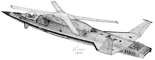
Here is something similar to the Scissorwing. The Sikorsky X-Wing. It spins up to take off like a helicopter then the blades slow and lock into an X as speed increases. The most unique feature is the symmetrical blade that is converted into a continuously changing airfoil shape during rotation by high speed compressors and little flapper valves on the leading and trailing edges. The "wing" is literally made of compressed air. I was there when they laid the fabric for the blades then sent to Edwards for testing on the Rotary Wing Research Test Vehicle. In the mid-1980's I flew everything that came out the door at Sikorsky including variants of the H-60, H-53, H-3 and various project aircraft.
The Sikorsky X-Wing was an experimental hybrid helicopter/fixed-wing aircraft developed between 1983 and 1988 by helicopter manufacturer Sikorsky with NASA and DARPA funding. Intended to take off vertically like a helicopter, the craft's rigid rotors could be stopped in mid-flight to act as X-shaped wings to provide additional lift during forward flight, as well as having more conventional wings.
Instead of controlling lift by twisting its blades as more conventional helicopters do, the craft used compressed air fed from the engines and expelled from its blades to generate a virtual wing surface, similar to blown flaps on a conventional platform. Computerized valves made sure the compressed air came from the correct edge of the rotor, the correct edge changing as the rotor rotated. This approach appears to have been abandoned for the tilt rotor configuration employed by the V-22 Osprey.
My drawing of the concept aircraft (Sikorsky security actually came and visited me over the weapons and protection gear I drew on the aircraft): Dennis Brooks
Specifications for the Ames-Dryden AD-1
 |
Length: 38 ft 4 in Wingspan: 32 ft spread, 16 ft 2 in swept Height: 6 ft 6 in Wing area: 93 sq ft Gross weight: 2,000 lb Powerplant: 2 × Ames TRS-18 turbojet, 220 lbf thrust each |