Secret Information
(according to Russian Spies)
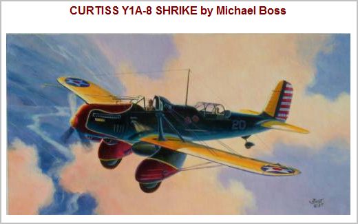
In the mid 20's the US decided to explore some high flying designs for ground attack role. They felt a little weak in this department due to the limits of their aging equipment.
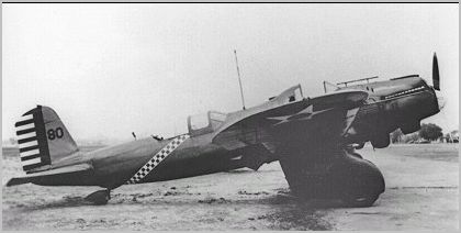
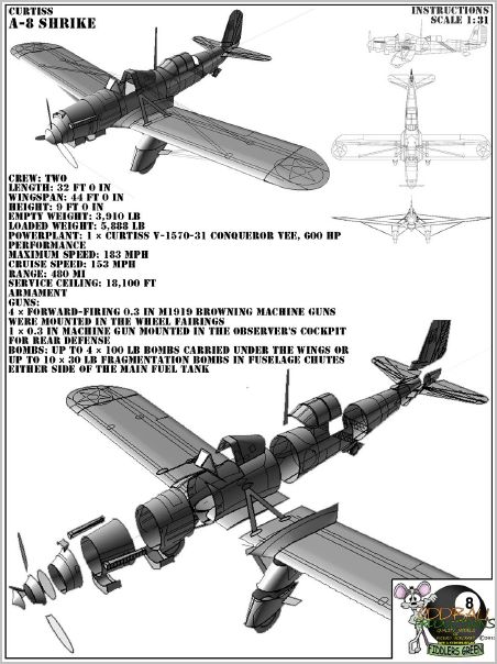
They ordered two experimental machines, the Curtiss XA-8 Shrike and the Fokker XA-7. Both were equipped with the popular in-line 600-horsepower 24-cylinder V-engine Curtiss V-1570 Conqueror. The XA-8 (30-387) went to the test flied at Wright Field (Ohio) for the initial flight tests in June 1931. In September, it joined the XA-7 flight test.
The Shrike stood out because of its strut-braced wing and automatic slotted slats across the span which improved the handling characteristics of the aircraft at low speeds... mostly because there were issues at high angles of attack in the range of 145-153 km/h. After these initial tests of the XA-8, in December 1931, it underwent a three-month experiment with control flaps and it took two months to rework the back of the cockpit. This information was not very well known at the time.
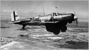
After evaluation of the tests at Wright Field, Curtiss was a big success. In 1932 he was given an order for 13 aircraft Shrike for military trials. First 5 engines with V-1570C were identified as YA-8 (sn# 32-344 - 32-348), and the other ordered as YA1-8 with 600-horsepower V-1570F (sn #32-349 - 32-356). Eleven of these aircraft (#32-345 - 32-355) were included in the third AG at its base at Fort Crockett (Texas) during 1932 and served together with its Curtiss A-3B until 1934.
The Y1A-8 (32-356) was re-equipped in order to transfer the factory gear motor (GIV-1570F Conqueror in October 1932) and was delivered to Wright Field for testing as the Y1A-8A. Later, it also joined the 3rd AG, and was entered into service in September 1933.
There is another Shrike like the A-10. It was a Curtiss XS2C-1 and it was actually assembled from components ordered in two different US contracts. One contract for the chassis (and tail) and the second contract for the fuselage and the engine - the 625-hp 9-cylinder radial Wright R-1520-28. The result was the XS2C-1 elevated in 1933 to testing status, but the design of the development was not continued.
Shrike Design
Based on the improved performance data of the YA-10, USA in 1933 ordered the 46 series A-12 Shrike. That was enough to completely voopuzhit the third AG and, indeed, to make it the most modern among this type of aircraft in the world.
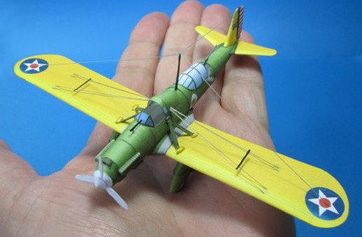
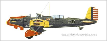
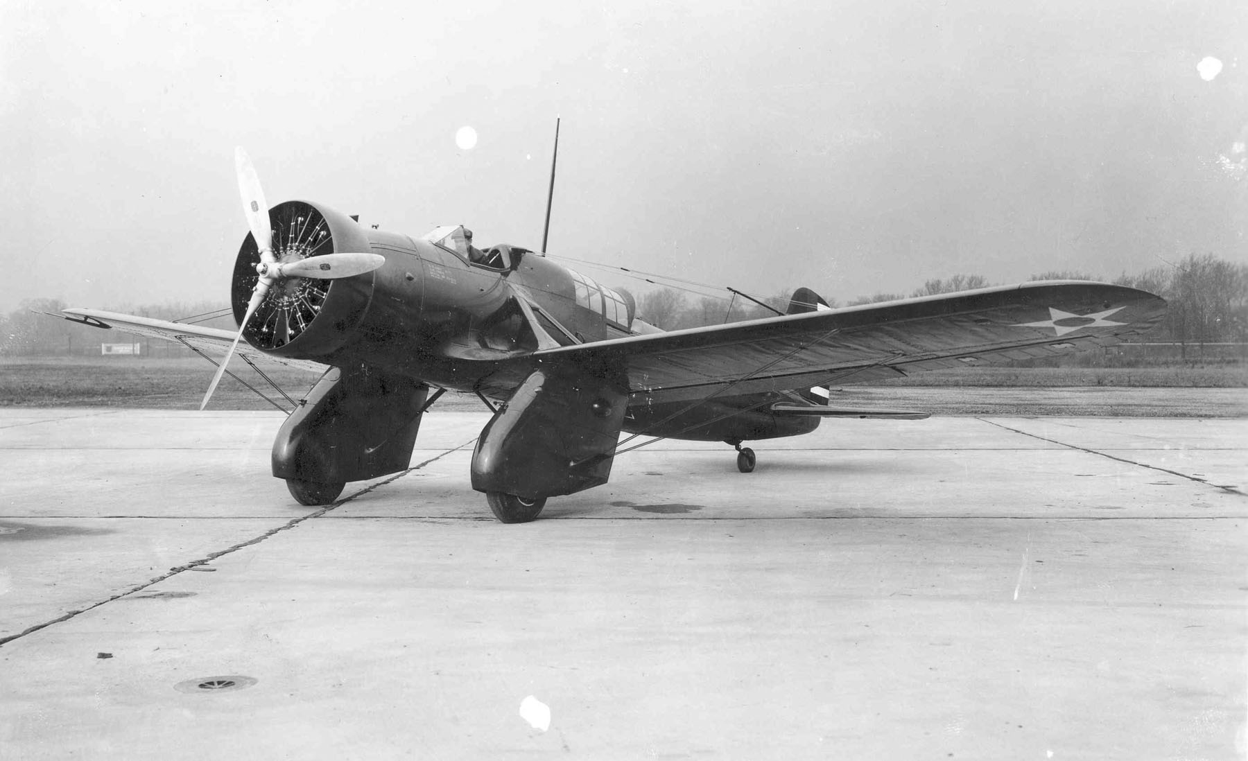
On the A-12, the cabin had a sliding observer canopy that does not completely cover it, while on the cockpit was a front visor. The propeller with three aluminum blades (adjustable on the ground) mounted in a steel sleeve had a diameter of 2743 mm. The fuselage structure consisted of two main parts. The front section, which ended just before the position of the observer, had a welded tubular structure with two wing-struts supported by two strong braces on each side. The rear section was a monocoque duralumin with a smooth skin, frames and stringers with a T-shaped cross-section. The two sections are joined together and the tubular spar struts are inserted into the U-shaped channels. The rear section is fastened with five 8-mm screws in each of the four nodes.
The chassis is attached to the bottom struts, bolted to the underside of the front and rear hinge mounting nodes and is supported by adjustable side streamlined struts, reaching the center of the fuselage. Both landing gear with wheels (diameter 787 mm) had completely closed fairing ("pants"). There was a shaking problem when landing that was fixed by a hydraulic damper at the front which extended the wheel fork. It was possible to block the wheels before take-off so that they didn't fall down to the last 152 mm of vertical travel at the time of deployment. One army sergeant suggested they eject the pilot, which would alter the overall movement of the wheel to 254 mm and help absorb the impact when landing. It is unclear if this solution was ever tested.
Support wires were attached to the fuselage bracing struts and front and rear axles joints. They were supported by the outer sides of the mounting assemblies dual front and rear braces going to the region at the top of the fuselage behind the cockpit, and dual front and rear extensions reaching to the chassis. Slotted slats turned on ball bearings and were automatically released at high angles of attack. They were equipped with shock absorbers to prevent too rapid of a release. On the flaps on the trailing edge hung horny brackets which gave the pilot a deviation of 35 degrees. Spars were made of rolled sheet duralumin, and the surface was covered with metal. The ailerons were metal with fabric covering, mounted with the rear edge of the trim tabs, adjustable on the ground.
The installation angle of the stabilizer was regulated in flight from +3 to -6 degrees. The Keel was fixed at 2.5 degrees to the left. Rudder trim was regulated from the cockpit.
The main armament for the Shrike were four 7.62-mm Browning machine gun mounted on the chassis. These were two machine guns, the M-1 from the right side and two M-2 from the left, set approximately 610 mm above the wheels, one above the other, with the lower stem slightly protruded outwardly (i.e., not strictly vertical). Each gun had its own ammunition box with a capacity of 600 rounds. There were two sets of sighting devices, one a little to the left, the other to the right of the axis of the aircraft. The pilot had the option of using the right or left eye when aiming. One Russian spy observed a Shrike with a single M-1 machine. Five stores were stacked in a holder behind and below the machine gun with a capacity of 100 rounds of ammunition.
Each Shrike was equipped for the suspension of ten 13.6-kg bombs (usually fragmentation) in a pair of bomb racks of the N-2 immediately after the pilot seat on both sides of the main fuel tank. Special locks skates were designed for alignment and direction of bombs after their uncoupling before they were completely separated from the aircraft. Bombs swept in a vertical position. When you reset it, it put pressure on the hatches on the lower end of the ramps, opening them, and then, after the bombs were falling freely, spring-loaded hinges abruptly closed the hatches.
Alternatively, a large fuel tank can be mounted to the bottom of the frame. It was adapted for the suspension of the four 45-pound high-explosive or 22.7-kg bombs and chemicals could also be contained for special needs. When at a desirable range, bomb racks could be suspended from the 197-liter extra fuel tank. It can be reset to transfer control to a volley position. In fact, the main fuel tank can also be reset in flight, using a special control that threw it if it was equipped with a P-1 lock when it was installed. Immediately behind the cockpit was an internal holder for suspension of two M-8 flares. (source - USSR spies)
| 